
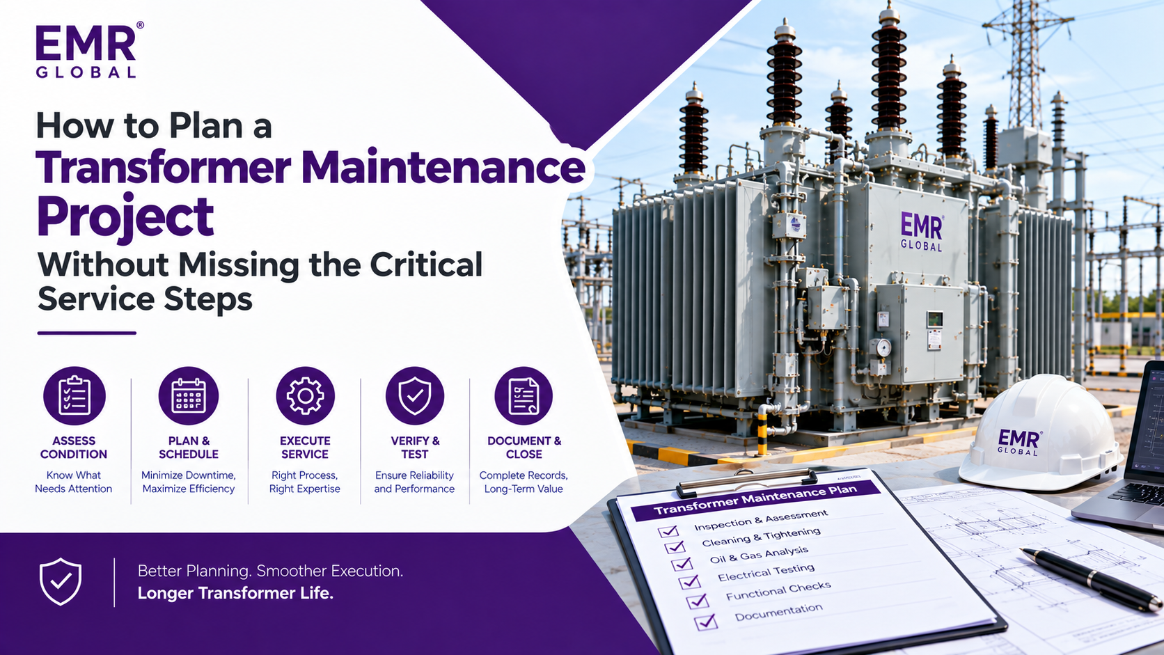
How to Plan a Transformer Maintenance Project Without Missing the Critical Service Steps
Why This Guide Exists
Every experienced transformer engineer has a story about a maintenance project that went sideways, not because the technical work was wrong, but because something upstream of the technical work wasn't planned correctly. The wrong spares were ordered. The testing sequence was wrong and had to be repeated. The outage window was too short for the actual scope. The vendor wasn't available when they were needed.
This guide uses one real maintenance project as a teaching example — a 19-year-old, 220 kV power transformer with an approaching OLTC maintenance interval — to walk through the planning steps that make the difference between a maintenance project that comes in on time with a clean return-to-service record and one that doesn't.
Step 1: Condition Review Before You Write the Scope
The first planning step is not writing the maintenance plan. It is reviewing every available piece of condition data and asking whether the planned scope reflects what the data actually shows.
For the example transformer, the available condition data included four quarters of DGA sampling results, a visual inspection report from the previous outage, the OLTC switching count since the last diverter switch service, and the motor drive operation log from the motor drive unit's internal counter.
The DGA results appeared within limits but had been taken from the upper oil layer — not representative of the heavier contamination settled at the bottom of the OLTC compartment. The switching count was within the maintenance interval limit but approaching it. The visual inspection had flagged minor oil discolouration without recommending action.
A condition review that asked "what is the worst reasonable case for actual condition given this data?" would have identified the possibility that the contact wear was beyond the replacement threshold and that the oil condition was worse than the upper-layer sample showed. That possibility should drive the scope to include contingency for full diverter switch overhaul and full oil change, with the final scope confirmed by Day 1 inspection findings.
Step 2: Outage Window Sizing — Build in Scope Contingency
The outage window for a standard OLTC service on a 220 kV transformer is typically three to four days. The outage window for a full diverter switch overhaul, full oil change, motor drive servicing, and OSR relay calibration is five to seven days.
If the condition review has identified a reasonable possibility of the more extensive scope, the outage window should be sized for the more extensive scope — with a clause in the shutdown coordination that an earlier return-to-service is possible if the Day 1 inspection confirms better-than-expected condition.
The alternative — sizing the window for the optimistic scope and discovering on Day 1 that the actual scope is larger — produces pressure on every subsequent decision and typically results in a return-to-service date that overshoots the original window by more than the contingency would have added.
Step 3: Inspection Planning — What to Look for on Day 1
The Day 1 inspection is the scope confirmation event. The following sequence covers the critical assessment points for an OLTC service project:
OLTC compartment entry: Oil level check, oil colour and odour assessment, visual inspection of the conservator connection and OSR pipeline for abnormality before the compartment is opened.
Diverter switch removal and assessment: Contact surface measurement against the OEM wear limit specification. Transition resistor visual inspection and resistance measurement. Drive mechanism inspection for mechanical play and corrosion. Record all measurements against the specification limits — not against previous inspection values alone.
Oil sampling: Representative sample from the compartment drain point at the bottom of the diverter switch oil volume — not from the upper conservator connection. Test for dielectric breakdown voltage, moisture content, acidity, and carbon particulate content before proceeding with oil change planning.
Motor drive inspection: Manual operation of the drive linkage to assess mechanical play. Operational test through the full tap range with current monitoring on the motor drive circuit to identify timing anomalies.
Bushing visual inspection: Examination of all bushing flanges for oil seepage or seal weep. Thermography data review if available from online monitoring. Physical inspection of the terminal connector condition and torque.
OSR relay verification: Simulated flow test at calibrated flow rates to confirm the trip threshold is set correctly for the specific OLTC design's normal oil-surge characteristics.
Step 4: Spares — Tiered Ordering Before the Window Opens
Spares for a transformer maintenance project should be ordered in two tiers, placed before the outage window opens:
Tier 1 — Confirmed scope spares: The components required for the maintenance plan's expected scope. Contact sets for the wear condition predicted by the switching count and DGA history. Oil in the quantity required for a top-up plus 20% margin. Motor drive service kit for the adjustment scope anticipated by the condition review.
Tier 2 — Contingency spares: The components most likely to be needed if the Day 1 inspection confirms worse-than-expected condition. A complete diverter switch overhaul kit including transition resistors. Additional oil for a full compartment drain and refill. Motor drive linkage components for the linkage replacement scope.
Tier 2 spares should be ordered on a return-if-unused basis where the supplier relationship permits this arrangement. The cost of holding Tier 2 spares for three days and returning them unused is negligible compared to the cost of emergency sourcing under outage pressure.
EMR Global's spares team can support both tiers — identifying the correct components for specific OLTC designs, confirming material specifications, and arranging delivery timing aligned to the outage window. Establishing this supply contact before the outage opens, not during it, is the planning step that makes the tiered ordering approach viable.
Step 5: Testing Sequence — In the Right Order
The testing sequence after OLTC service completion should follow a defined order that prevents repeated test failures caused by out-of-sequence verification:
- Contact resistance measurement on the reassembled diverter switch before oil filling — confirming the contact assembly is correct before the compartment is sealed.
- Oil compartment seal pressure test before oil filling — confirming there are no leak paths before oil is introduced.
- Oil fill with tested, specification-grade degassed oil — confirming oil quality test results before filling.
- OLTC operational test through the full tap range after oil filling — confirming the mechanism operates correctly in the oil environment.
- Turns ratio verification at each tap position — confirming the OLTC is delivering the correct turns ratio at every position.
- OSR relay operational verification after the pipeline is reconnected — confirming the relay responds correctly at its calibrated threshold.
- Motor drive communications verification — confirming SCADA and IEC 61850 communications are operational after the motor drive has been serviced.
- Return-to-service checklist sign-off — all tests completed and recorded, all documentation filed, all isolation removed in the correct sequence.
Step 6: Return-to-Service Checks
Before the transformer is re-energised, the following checks should be completed and signed off:
- All access covers reinstalled and torqued to specification
- All oil fill and drain valves returned to service position
- Buchholz relay gas pocket verified clear
- OSR relay pipeline verified gas-free
- Motor drive local/remote selector in remote position
- Tap position indicator verified aligned to actual tap position
- Protection relay alarms and trips verified clear and reset
- SCADA return-to-service notification sent to control centre
- First post-energisation oil sample scheduled for 24 hours after return to service
The 24-hour post-energisation oil sample is an often-omitted but valuable step — it establishes the baseline from which future oil condition monitoring will trend, and it can detect early signs of abnormal gas generation from a fault that the service may have disturbed rather than resolved.

 English
 French
 Spanish
 Portuguese
 Deutsch
 Turkish
 Dutch
Dutch
 Italiano
 Russian
 Romaian
 Portuguese (Brazil)
 Greek
Greek